SPONSORED LINKS
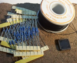 Assemble parts. Assemble parts. |
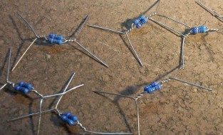 Twist resistors together. Twist resistors together. |
 Twist resistors together some more. Twist resistors together some more. |
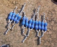
 Solder joints and bend leads upward. Put aside. Solder joints and bend leads upward. Put aside. |
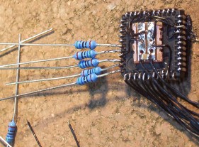 Stick
IC to work surface with double sided tape. A small piece of verro strip
board is glued to the centre of the IC. It holds the bypass capacitor
provides a common point to connect ground and VCC wires. Solder 140mm
wires to the inputs of the IC. Then start with the resistors. Stick
IC to work surface with double sided tape. A small piece of verro strip
board is glued to the centre of the IC. It holds the bypass capacitor
provides a common point to connect ground and VCC wires. Solder 140mm
wires to the inputs of the IC. Then start with the resistors. |
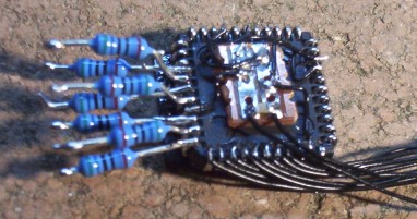 Bend up every second resistor, trim the leads, then add some solder. Bend up every second resistor, trim the leads, then add some solder. |
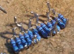
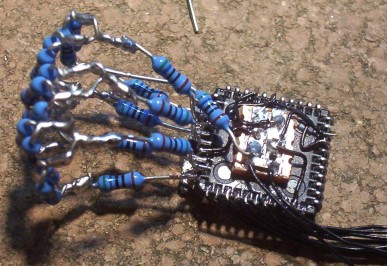 Solder two resistor sections together. Add resistor R20 from bit0 to ground. Solder two resistor sections together. Add resistor R20 from bit0 to ground. |
 Now do it again. And again. Now do it again. And again. |
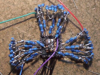
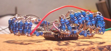 Resistors should float, not touch the surface. Resistors should float, not touch the surface. |
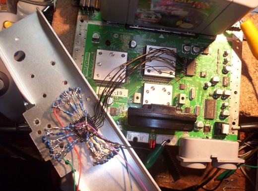 Connect input wires to the Nintendo DAC and test. If everything is ok then glue into position on heat sink. Connect input wires to the Nintendo DAC and test. If everything is ok then glue into position on heat sink. |